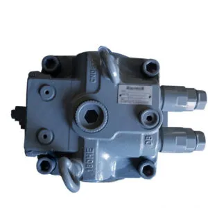
Ko je krmilni ročaj v položaju za vrtenje, krmilno olje doseže krmilni ventil in potisne palico vrtljivega ventila, da se visokotlačno olje, ki ga zagotavlja zadnja črpalka delovnega olja, dovede v vrtljivi motor; Hkrati se prekine oljni krog, ki nadzoruje vračanje olja v rezervoar, kar poveča tlak v sprostitvenem zavornem ventilu, potisne njegovo ventilno steblo in omogoči, da v zavorni bat pride še eno olje pod dodatnim pritiskom, kar odpre napravo nihajne zavore in povzroči delovanje vrtljivega motorja; vrtljivi motor oddaja moč prek malega zobnika menjalnika, ki se zagozdi z vrtljivim obročem in ustvari vrtljivo gibanje.
From the working principle of the rotary mechanism, there are three reasons for the malfunction, namely the main working oil circuit, mechanical transmission, and control oil circuit.
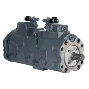
If the pressure of the swing main oil circuit is low, it will not be possible to generate swing action. Measure the pressure of the main working oil circuit system. There is an internal hexagonal oil plug at the pressure outlet of the rear working oil pump. Remove it and install a pressure gauge. Operate the rotary handle to accelerate the diesel engine. The measured pressure reaches 23.5MPa, which is the normal working pressure of the system. This indicates that all hydraulic components in the main working oil circuit are normal.
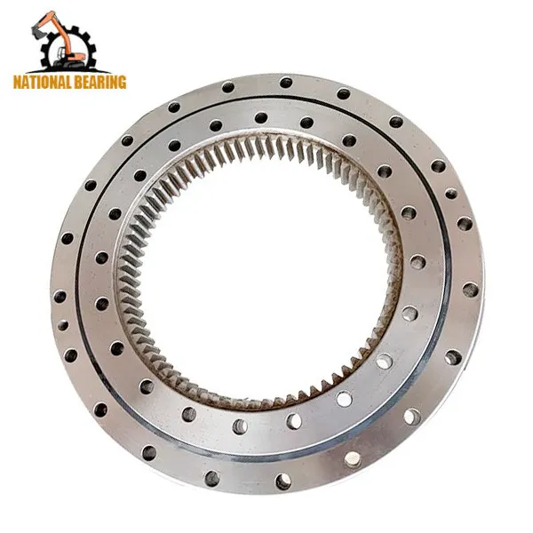
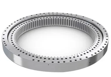
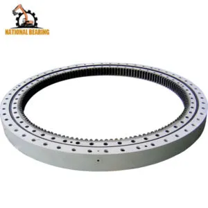
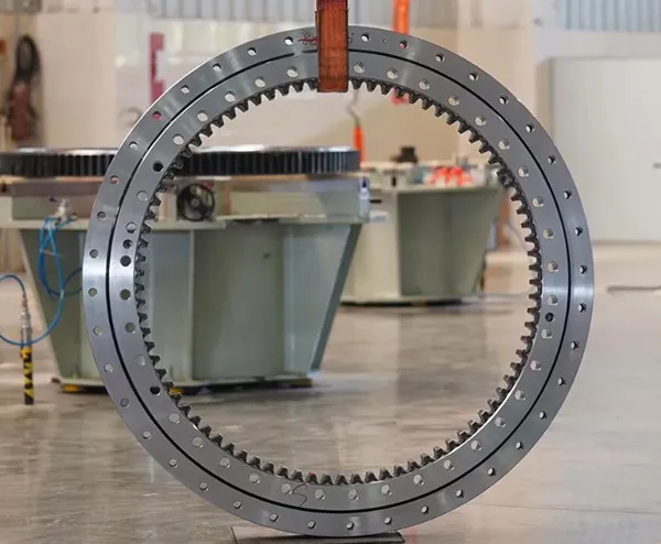
The rotary motor outputs power through the small gear of the transmission, which rotates around the rotary gear ring. During this power output process, if the gears that mesh with each other are jammed, there will also be no rotation action.
Generally, abnormal gear engagement can cause abnormal noise. Currently, the driver has not heard any abnormal sound during operation, so mechanical transmission faults can be temporarily ruled out.
Since all other actions of the excavator are normal, it indicates that the auxiliary oil pump that provides control oil pressure is working normally. There are three control oil circuits for the rotary action, namely the oil circuit that controls the rotary valve stem, brake release valve, and the oil circuit that enters the parking brake piston. The specific analysis is as follows.
When operating the rotary handle, there is a strong oil flu when touching the pressure oil pipe of the rotary motor, indicating that the main working pressure oil has reached the rotary motor, the rotary valve stem of the control valve can be opened normally, and the control oil circuit is working normally. Measure the oil pressure to the parking brake piston. Open the pipe joint of the oil circuit to the rotary motor, install the three-way joint and pressure gauge, and the measured pressure reaches 4MPa, indicating that the pressure of the oil circuit is normal.
Measure the oil pressure to the brake release valve. Open the pipe joint of the oil circuit to the rotary motor, install the three-way joint and pressure gauge, and the measured pressure is 0.4-0.6MPa. Obviously, this pressure is too low (normal working pressure should be 4MPa) to open the brake release valve, and the control oil from the other circuit cannot flow into the brake piston, let alone open the rotary brake device. Therefore, there is no action in the rotation. There are two reasons for the low pressure in this oil circuit. One is that the control valve leaks, causing the oil pressure entering the brake release valve to decrease. (Connect the pressure gauge to the pipe joint of the control oil pipe from the control valve to the brake release valve, and the measured oil pressure is only 0.4-0.6MPa, indicating that the judgment of the control valve leaking is correct.); The second reason is that the brake release valve leaks due to wear and tear, which increases the fit gap (after disassembly and inspection, the valve stem and valve hole fit well and there is no jamming phenomenon).
Excavators are complex pieces of machinery that rely heavily on their hydraulic systems to perform a variety of tasks, from digging and lifting to rotating and moving. One of the critical components in this hydraulic system is the control valve. The control valve regulates the flow and direction of hydraulic fluid, enabling precise control over the excavator’s movements. However, when a malfunction occurs, it can severely impact the performance and efficiency of the machine. This detailed guide delves into the process of troubleshooting a control valve malfunction, including the steps taken to diagnose the issue, the repair process, and the measures to prevent future problems.
Control valves are essential for directing hydraulic fluid to different parts of the excavator. They are responsible for controlling the flow rate and pressure of the hydraulic fluid, which in turn controls the speed and force of the machine’s movements. The primary functions of control valves in an excavator include:
Given their critical role, any malfunction in the control valve can lead to significant operational issues, such as erratic movements, reduced power, and complete failure of specific functions.
Before diving into the troubleshooting process, it’s essential to recognize the common symptoms of control valve malfunctions. These symptoms can help in early detection and prompt action to prevent further damage to the excavator. Common signs of control valve issues include:
The first step in troubleshooting a control valve malfunction is a thorough diagnosis. This involves a systematic approach to identify the root cause of the problem. Here’s a detailed breakdown of the diagnostic process:
Begin with a visual inspection of the control valve and the surrounding hydraulic components. Look for signs of wear, damage, or leaks. Pay close attention to the following:
The condition of the hydraulic fluid can provide valuable insights into the health of the control valve and the entire hydraulic system. Perform the following checks:
Pressure testing the hydraulic system can help identify issues related to fluid flow and pressure regulation. Use a hydraulic pressure gauge to perform the following tests:
Conduct functional tests to observe the performance of the control valve under different operating conditions. These tests can help pinpoint specific issues:
In this case study, the primary symptom observed was erratic rotational movements of the excavator. Upon conducting the above diagnostic steps, it was determined that the main cause of the malfunction was leakage in the control valve. Here’s a detailed analysis of the findings:
During the visual inspection, hydraulic fluid leaks were detected around the control valve area. The seals and gaskets appeared worn and deteriorated, indicating a potential source of the leakage.
The hydraulic fluid analysis revealed contamination with particles and moisture, which can accelerate wear and damage to the control valve components. The fluid’s color and viscosity suggested that it had not been changed according to the recommended maintenance schedule.
Pressure testing indicated significant pressure drops across the control valve, confirming internal leaks. The system pressure was also lower than the manufacturer’s specifications, further supporting the diagnosis of valve leakage.
Functional testing showed inconsistent and weak rotational movements, which aligned with the symptoms of control valve leakage. The directional control was also affected, with delays and difficulties in changing directions.
Given the complexity and critical role of the control valve, repairing it requires careful attention and expertise. Here’s a step-by-step guide to the repair process:
To access and repair the control valve, it is necessary to remove it from the excavator. This involves the following steps:
Once the control valve is removed, disassemble it to inspect and replace the damaged components. This involves:
After replacing the damaged components, reassemble the control valve with careful attention to detail:
With the control valve repaired and reassembled, reinstall it into the excavator:
After reinstalling the control valve, perform comprehensive tests to ensure that the repair was successful:
To prevent future control valve malfunctions and ensure the longevity of the excavator’s hydraulic system, implement the following maintenance practices:
Regularly check the hydraulic fluid level and quality, and change it according to the manufacturer’s recommendations. Using clean, high-quality hydraulic fluid helps prevent contamination and reduces wear on the control valve components.
Inspect seals and gaskets regularly for signs of wear and deterioration. Replace them as needed to prevent leaks and maintain optimal pressure within the hydraulic system.
Implement a regular maintenance schedule that includes checking the condition of the control valve, hydraulic lines, and other components. Timely maintenance helps identify and address potential issues before they lead to significant malfunctions.
Ensure that operators are trained in the correct use and maintenance of the excavator’s hydraulic system. Proper operation and handling can reduce the risk of damage and prolong the lifespan of the control valve and other components.
Always use genuine parts and components that meet the manufacturer’s specifications when repairing or replacing parts of the hydraulic system. This ensures compatibility and reliability, reducing the risk of future malfunctions.