Quando o manípulo de operação é colocado na posição rotativa, o óleo de controlo atinge a válvula de controlo e empurra a haste da válvula rotativa para alimentar o óleo de alta pressão fornecido pela bomba de óleo de trabalho traseira para o motor rotativo; Ao mesmo tempo, o circuito de óleo que controla o retorno do óleo ao depósito é cortado, aumentando a pressão da válvula de libertação do travão, empurrando a haste da válvula para permitir a entrada de outro óleo de pressão auxiliar no pistão do travão, abrindo o dispositivo do travão de oscilação e fazendo com que o motor de oscilação actue; O motor rotativo produz potência através da pequena engrenagem da caixa de velocidades, que engrena com o anel da engrenagem rotativa para gerar um movimento rotativo.
De acordo com o princípio de funcionamento do mecanismo rotativo, existem três razões para o mau funcionamento, nomeadamente o circuito principal de óleo de trabalho, a transmissão mecânica e o circuito de óleo de controlo.
Se a pressão do circuito principal de óleo de oscilação for baixa, não será possível gerar uma ação de oscilação. Medir a pressão do sistema do circuito principal de óleo de trabalho. Existe um bujão de óleo hexagonal interno na saída de pressão da bomba de óleo de trabalho traseira. Retire-o e instale um manómetro. Acionar o manípulo rotativo para acelerar o motor diesel. A pressão medida atinge 23,5 MPa, que é a pressão normal de funcionamento do sistema. Isto indica que todos os componentes hidráulicos do circuito principal do óleo de trabalho estão normais.
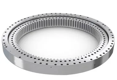
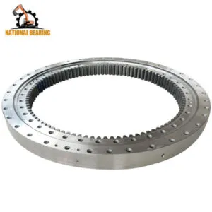
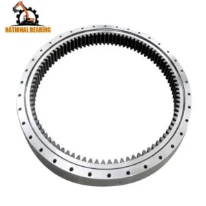
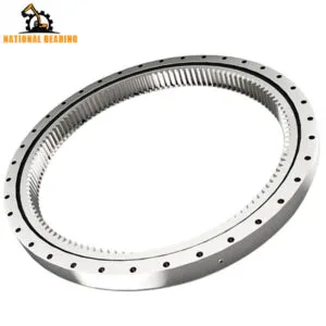
O motor rotativo produz energia através da pequena engrenagem da transmissão, que gira em torno do anel de engrenagem rotativo. Durante este processo de saída de potência, se as engrenagens que engrenam entre si estiverem encravadas, também não haverá ação de rotação.
Geralmente, um engate anormal da mudança pode provocar um ruído anormal. Atualmente, o condutor não ouviu qualquer som anormal durante o funcionamento, pelo que as falhas mecânicas da transmissão podem ser temporariamente excluídas.
Uma vez que todas as outras acções da escavadora são normais, isso indica que a bomba de óleo auxiliar que fornece a pressão do óleo de controlo está a funcionar normalmente. Existem três circuitos de óleo de controlo para a ação rotativa, nomeadamente o circuito de óleo que controla a haste da válvula rotativa, a válvula de libertação do travão e o circuito de óleo que entra no pistão do travão de estacionamento. A análise específica é a seguinte.
Ao acionar o manípulo rotativo, há um forte fluxo de óleo ao tocar no tubo de óleo de pressão do motor rotativo, indicando que o óleo da pressão de trabalho principal chegou ao motor rotativo, a haste da válvula rotativa da válvula de controlo pode ser aberta normalmente e o circuito de óleo de controlo está a funcionar normalmente. Medir a pressão do óleo no pistão do travão de estacionamento. Abrir a junta do tubo do circuito de óleo para o motor rotativo, instalar a junta de três vias e o manómetro, e a pressão medida atinge 4MPa, indicando que a pressão do circuito de óleo é normal.
Medir a pressão do óleo na válvula de libertação do travão. Abrir a junta do tubo do circuito de óleo para o motor rotativo, instalar a junta de três vias e o manómetro, e a pressão medida é de 0,4-0,6MPa. Obviamente, esta pressão é demasiado baixa (a pressão de trabalho normal deve ser de 4MPa) para abrir a válvula de libertação do travão, e o óleo de controlo do outro circuito não pode fluir para o pistão do travão, muito menos abrir o dispositivo do travão rotativo. Por conseguinte, não há ação na rotação. Há duas razões para a baixa pressão neste circuito de óleo. Uma é que a válvula de controlo tem fugas, fazendo com que a pressão do óleo que entra na válvula de libertação do travão diminua. (Ligue o manómetro à junta do tubo de óleo de controlo da válvula de controlo à válvula de libertação do travão e a pressão do óleo medida é de apenas 0,4-0,6 MPa, o que indica que a avaliação da fuga da válvula de controlo está correcta); a segunda razão é que a válvula de libertação do travão tem fugas devido ao desgaste, o que aumenta a folga de ajuste (após a desmontagem e a inspeção, a haste da válvula e o orifício da válvula encaixam bem e não há qualquer fenómeno de encravamento).
As escavadoras são peças complexas de maquinaria que dependem fortemente dos seus sistemas hidráulicos para executar uma variedade de tarefas, desde escavar e elevar até rodar e deslocar. Um dos componentes críticos deste sistema hidráulico é a válvula de controlo. A válvula de controlo regula o fluxo e a direção do fluido hidráulico, permitindo um controlo preciso dos movimentos da escavadora. No entanto, quando ocorre uma avaria, esta pode afetar gravemente o desempenho e a eficiência da máquina. Este guia detalhado analisa o processo de resolução de problemas de uma avaria da válvula de controlo, incluindo os passos dados para diagnosticar o problema, o processo de reparação e as medidas para evitar problemas futuros.
As válvulas de controlo são essenciais para direcionar o fluido hidráulico para diferentes partes da escavadora. São responsáveis pelo controlo do caudal e da pressão do fluido hidráulico, que, por sua vez, controla a velocidade e a força dos movimentos da máquina. As principais funções das válvulas de controlo numa escavadora incluem:
Dado o seu papel crítico, qualquer avaria na válvula de controlo pode levar a problemas operacionais significativos, tais como movimentos erráticos, redução da potência e falha completa de funções específicas.
Antes de mergulhar no processo de resolução de problemas, é essencial reconhecer os sintomas comuns de avarias nas válvulas de controlo. Estes sintomas podem ajudar na deteção precoce e na ação imediata para evitar mais danos na escavadora. Os sinais comuns de problemas na válvula de controlo incluem:
O primeiro passo na resolução de problemas de avaria de uma válvula de controlo é um diagnóstico completo. Isto envolve uma abordagem sistemática para identificar a causa raiz do problema. Segue-se uma descrição pormenorizada do processo de diagnóstico:
Comece por uma inspeção visual da válvula de controlo e dos componentes hidráulicos circundantes. Procure sinais de desgaste, danos ou fugas. Preste muita atenção ao seguinte:
O estado do fluido hidráulico pode fornecer informações valiosas sobre o estado da válvula de controlo e de todo o sistema hidráulico. Efectue as seguintes verificações:
O teste de pressão do sistema hidráulico pode ajudar a identificar problemas relacionados com o fluxo de fluido e a regulação da pressão. Utilize um manómetro de pressão hidráulica para efetuar os seguintes testes:
Realizar testes funcionais para observar o desempenho da válvula de controlo em diferentes condições de funcionamento. Estes testes podem ajudar a identificar problemas específicos:
Neste estudo de caso, o principal sintoma observado foram os movimentos de rotação erráticos da escavadora. Após a realização dos passos de diagnóstico acima referidos, foi determinado que a principal causa da avaria era uma fuga na válvula de controlo. Segue-se uma análise detalhada dos resultados:
Durante a inspeção visual, foram detectadas fugas de fluido hidráulico na zona da válvula de controlo. Os vedantes e as juntas pareciam estar gastos e deteriorados, indicando uma fonte potencial de fugas.
A análise do fluido hidráulico revelou contaminação com partículas e humidade, o que pode acelerar o desgaste e danificar os componentes da válvula de controlo. A cor e a viscosidade do fluido sugeriam que este não tinha sido mudado de acordo com o calendário de manutenção recomendado.
Os testes de pressão indicaram quedas de pressão significativas na válvula de controlo, confirmando a existência de fugas internas. A pressão do sistema também era inferior às especificações do fabricante, apoiando ainda mais o diagnóstico de fuga na válvula.
Os testes funcionais revelaram movimentos de rotação inconsistentes e fracos, que se alinhavam com os sintomas de fuga na válvula de controlo. O controlo direcional também foi afetado, com atrasos e dificuldades na mudança de direção.
Dada a complexidade e o papel crítico da válvula de controlo, a sua reparação requer uma atenção cuidada e conhecimentos especializados. Aqui está um guia passo-a-passo para o processo de reparação:
Para aceder e reparar a válvula de controlo, é necessário retirá-la da escavadora. Isto envolve os seguintes passos:
Uma vez retirada a válvula de controlo, desmonte-a para inspecionar e substituir os componentes danificados. Isto envolve:
Depois de substituir os componentes danificados, volte a montar a válvula de controlo com uma atenção cuidadosa aos detalhes:
Com a válvula de controlo reparada e montada de novo, reinstale-a na escavadora:
Depois de reinstalar a válvula de controlo, efetuar testes exaustivos para garantir que a reparação foi bem sucedida:
Para evitar futuras avarias nas válvulas de controlo e garantir a longevidade do sistema hidráulico da escavadora, implemente as seguintes práticas de manutenção:
Verifique regularmente o nível e a qualidade do fluido hidráulico e substitua-o de acordo com as recomendações do fabricante. A utilização de fluido hidráulico limpo e de alta qualidade ajuda a evitar a contaminação e reduz o desgaste dos componentes da válvula de controlo.
Inspeccione regularmente os vedantes e as juntas quanto a sinais de desgaste e deterioração. Substitua-as se necessário para evitar fugas e manter uma pressão óptima no sistema hidráulico.
Implemente um programa de manutenção regular que inclua a verificação do estado da válvula de controlo, das linhas hidráulicas e de outros componentes. A manutenção atempada ajuda a identificar e resolver potenciais problemas antes que estes conduzam a avarias significativas.
Certifique-se de que os operadores recebem formação sobre a utilização e manutenção correctas do sistema hidráulico da escavadora. A operação e o manuseamento adequados podem reduzir o risco de danos e prolongar a vida útil da válvula de controlo e de outros componentes.
Ao reparar ou substituir peças do sistema hidráulico, utilize sempre peças e componentes genuínos que cumpram as especificações do fabricante. Isto assegura a compatibilidade e a fiabilidade, reduzindo o risco de futuras avarias.