
Let’s dive into the various factors that can lead to gear pitting and peeling:
a. Material, Hardness, and Defects
b. Poor Gear Accuracy
c. Inadequate Lubricating Oil
d. High Oil Levels
By understanding these factors and regularly checking and maintaining the gearbox, you can mitigate the risks of gear pitting and peeling, ensuring your excavator reducer operates smoothly and efficiently.
Answer: a. It is due to a broken tooth that causes the input shaft to lose its axial constraint, resulting in shaft misalignment.
b. It is caused by the loose fastening between the driven gear on the intermediate shaft and the shaft. In actual transmission, often due to insufficient interference between the driven gear and the intermediate shaft, the driven gear produces axial displacement relative to the intermediate shaft, which in turn causes axial displacement of the input shaft. Therefore, insufficient interference is the main reason for the gearbox shaft string.
c. The steering of the gearbox also has a certain impact on the serial shaft.
Answer: a. The lubricating oil is unqualified or has been used for too long.
b. Excessive lubricating oil is not conducive to the heat dissipation of the gearbox mechanism.
c. Damaged parts. Mechanical damage includes severe gear pitting, tooth breakage, damage to bearing cages, inner and outer rings, ball bearings, and severe bearing locking or shaft deformation;
d. The outside of the box is covered with debris or dust. When things are piled up around the reducer or the surface of the body is not cleaned for a long time, it is possible that the cover of debris or dust may cause incomplete heat dissipation of the reducer, resulting in an increase in oil temperature;
e. The cooling device is blocked or malfunctioning. The cooling device, like the gearbox, is placed in a dusty factory building. If the internal pipelines are not cleaned for a long time and the cooling device is blocked or damaged, it will cause an increase in the temperature of the gearbox oil;
Normal maintenance mainly includes:
Common faults mainly include:
The excavator reducer vibrates greatly; 2. There is noise; 3. High oil temperature; 4. Oil leakage; 5. Gear damage; 6 series axes; 7. Broken bearings.
3.1 Installation and Adjustment
a. To ensure the assembly accuracy of the reducer, it is not necessary to start the machine during installation and not damage the sealing glue. The rust proof grease on the surface of the gear can be checked by opening the sight oil cover or washed with kerosene (diesel).
b. Elastic couplings or gear couplings or other non rigid couplings can be used between the reducer and the motor or host.
c. The reducer should be installed steadily and firmly, and the base adjustment gasket must be firmly cut (using steel pads). The coaxiality deviation between the connecting parts shall not exceed the allowable value of the coupling device used.
d. Check if the bolts on each sealing surface of the box are loose, and if there is any looseness, tighten them again.
3.2 Use and Maintenance
a. Before the reducer is officially put into use, a load test must be conducted.
b. Before the load test, lubricating oil should be added according to the position of the oil mark, and the output shaft should be rotated by hand to make it rotate one circle, which must be flexible. Then, it should be idle for two hours and there should be no abnormal noise.
c. During the load test, the load should be gradually loaded to full load (if conditions permit, it should be loaded in four stages of 25%, 50%, 75%, and 100%), and each stage should run for no less than 2 hours. It should be stable and free of impact vibration and oil leakage. After confirming that there are no faults, the lubricating oil inside the machine should be drained or filtered with a 200 mesh filter before use.
d. If there are any abnormal situations during the test run, the cause should be identified, eliminated, and the manufacturer should be notified immediately.
e. The reducer should be repaired once every six months of operation, and the tooth surface should be checked regularly (weekly) for defects such as pitting, abrasion, and adhesion. If the defect area exceeds 20% along the tooth length and height direction and continues to develop, the gear pair should be replaced.
3.3 Lubrication
a. The gears adopt two forms of lubrication: oil pool lubrication and circulating lubrication. Lubricating oil is selected according to the equipment instructions. The soft tooth surface and medium hard tooth surface reducers use N100-150, while the hard tooth surface and planetary reducers use N220-320.
b. Lubricating oil should be regularly checked and replaced. When a newly installed reducer is first used, it must be replaced with new oil after 10-15 days of operation. In the future, the quality of the oil should be checked regularly (2-3 months), and if it does not meet the requirements, it should be replaced immediately. Generally, the oil should be changed at least every six months. When testing the quality of oil, if one of the following situations occurs, the lubricating oil must be replaced in a timely manner:
c. The daily maintenance and upkeep of the reducer mainly includes inspecting for oil leakage, timely checking the liquid level in the box, checking for good lubrication, checking the firmness and integrity of screws in all parts, regularly checking the temperature of the equipment, and using lead wire to bite into the meshing position of the gear during operation to measure tooth wear.
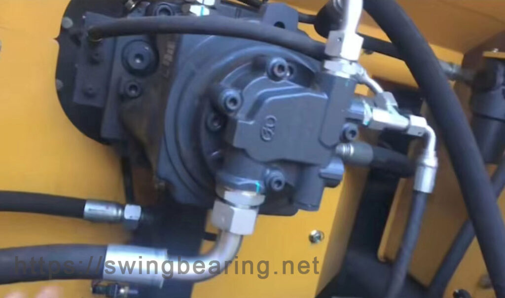
Possible faults that may occur during the use of the gearbox include oil leakage, overheating of the bearing area, loud noise, excessive temperature of the gearbox oil pool (above 70 degrees), abnormal noise from the gearbox, shifting of the driving shaft, bearing fragmentation, gear damage, etc. The causes and preventive measures are analyzed.
4.1 Gearbox oil leakage
4.1.1 Cause analysis:
There are various ways of oil leakage, but the most common is at the sealing points of the active and driven shaft heads, especially at the sealing ring of the active shaft, which is the most severe. In addition to the above situations, there are also three oil leakage areas.
a. Oil leakage along the gearbox joint surface;
b. Oil leakage at the sight hole cover on top of the reducer;
c. Oil leakage occurs at the drain hole at the bottom of the reducer;
The oil leakage at the sight hole cover and oil drain hole is mainly caused by the fixing bolts not being fully tightened or the sealing gasket not being installed.
During the assembly of individual gearboxes, there are iron shavings left on the box surface, causing the box surface to be loose and resulting in oil leakage. The reason for the oil leakage on the sealing surface is not only due to the above factors, but also more importantly, the deformation of the gearbox housing after a period of use, resulting in uneven sealing surface and loose fitting, leading to oil leakage.
4.1.2. Prevention and elimination methods:
a. The sealing ring cover adopts a detachable structure.
b. The sealing ring adopts an open structure.
c. The oil return hole at the input shaft bearing should be appropriately enlarged.
d. Performing aging treatment on the gearbox housing can prevent deformation and prevent oil leakage along the box surface. There are currently three methods for improving efficiency: one is natural failure; The second is artificial aging; The third is vibration aging. It can be selected and processed according to actual conditions.
e. A circular oil groove is cast or machined on the sealing surface of the reducer base, and there are multiple return oil holes connected to the circular oil groove. When the gearbox is in operation, once oil seeps into the gearbox surface, it will enter the annular oil groove and then flow into the oil tank through the oil return hole. Lubricating oil will not leak along the gearbox surface to the outside of the gearbox housing.
f. When assembling the gearbox, applying a layer of sealant (such as D05 silicone rubber sealant) on the joint surface can effectively prevent oil leakage at the joint surface.
g. If the oil level of the gearbox is too high, it not only increases the power loss of the gear stirring oil, but also increases the chance of oil leakage due to severe splashing of lubricating oil. It also leads to a continuous increase in oil temperature, especially in summer, when the ambient temperature is high, it will increase the oil temperature, decrease the viscosity of lubricating oil, reduce lubrication performance, increase the fluidity and leakage of oil, and directly affect the lubrication of gears and bearings, reducing their service life. Therefore, it is necessary to maintain a normal oil level during use.
h. Install sealing gaskets at the sight glass cover and oil drain hole, and tighten the bolts.
l. Increasing the return oil hole of the output shaft can prevent oil leakage from the output shaft.
j. Improve the breathable cap and inspection hole cover. One of the main reasons for oil leakage is that the internal pressure of the gearbox is greater than the external atmospheric pressure. If efforts are made to balance the pressure inside and outside the gearbox, oil leakage can be prevented. Although gearboxes all have breathable caps, the breathable holes are too small and can be easily blocked by dust and oil stains. Moreover, every time you refuel, you need to open the inspection hole cover plate, which increases the possibility of oil leakage and causes leaks in areas that were not originally leaking. Can increase the air permeability to achieve equal pressure inside and outside.
4.2 Overheating or noise in the bearing area of the gearbox
4.2.1 Cause analysis:
a. Utilstrekkelig smøreolje. Når smøreoljenivået er utilstrekkelig eller ikke kan nå en rimelig høyde på grunn av oljelekkasje i girkassen, kan det føre til høy temperatur eller støy i lagerområdet i girkassen;
b. Friksjon på lagerdekselet eller tetningsdelen. Når lageret er feil installert, lagerdekselet ikke er oppreist, eller det er slitasje på lagerdekselet eller tetningsdelen og tilkoblingsdelen på grunn av langvarig bruk, kan det føre til høy temperatur eller støy i reduksjonslageret;
c. Skadede eller slitte lagre. Hovedinnholdet i dette elementet er at lagerets holder er skadet, de indre og ytre ringene er slitt eller deformert, og kulelagrene er slitt eller falt ut, som alle kan føre til at reduksjonsgiret ikke fungerer normalt;
d. Lagerklaringen er for stor eller for liten. Når langvarig bruk fører til en økning i gapet mellom kulen og de indre og ytre ringene på reduksjonslageret, eller mellom de indre og ytre ringene på lageret og akselen, samt mellom lageret og endedekselet, kan de ovennevnte symptomene oppstå;
e. Håndtaket på tannhjulsnøkkelen er løst. Løst spindelnøkkelhåndtak kan føre til løs passform mellom tannhjulet og akselen, noe som kan føre til overoppheting av lageret eller støy;
4.2.2. Prevention and elimination methods:
a. Check the oil level and add lubricating oil;
b. Tighten the bolts of the bearings and connecting parts, and check the installation of the seals;
c. Check the bearings and replace them immediately if there is any damage;
d. If the clearance is not suitable, adjust the bearing clearance. If it cannot be adjusted, replace the bearing;
e. For loose helical gear keyshafts, timely repair should be sent;
4.3 Excessive gearbox oil temperature
4.3.1 Cause analysis:
a. Lubricating oil is unqualified or used too long. At present, the lubricating oil used in our group’s gearbox is mostly 320 # extreme pressure gear oil. If expired or different lubricating oil properties are added, or if the lubricating oil is not replaced for a long time, it may cause the gearbox oil temperature to be too high;
b. Excessive lubricating oil. When the height of the oil level is higher than the upper and lower limits of the dipstick or visible hole, it will cause the gearbox oil temperature to be too high;
c. Damaged parts. Mechanical damage includes severe gear pitting, tooth breakage, damage to bearing cages, inner and outer rings, ball bearings, and severe bearing locking or shaft deformation;
d. The outside of the box is covered with debris or dust. When things are piled up around the reducer or the surface of the body is not cleaned for a long time, it is possible that the cover of debris or dust may cause incomplete heat dissipation of the reducer, resulting in an increase in oil temperature;
e. The cooling device is blocked or malfunctioning. The cooling device, like the gearbox, is placed in a dusty factory building. If the internal pipelines are not cleaned for a long time and the cooling device is blocked or damaged, it will cause an increase in the temperature of the gearbox oil;
4.3.2. Exclusion method:
a. Replace lubricating oil;
b. Remove excess oil;
c. Carefully inspect and locate the damaged parts, repair or replace them in a timely manner;
d. Remove debris and dust;
e. Replace the cooling device or remove blockages;
4.4 Excessive vibration of the gearbox
4.4.1 Cause analysis:
a. Loose foundation screws. Due to long-term operation, the reducer may have loose or damaged ground screws, which can cause excessive vibration and abnormal working conditions;
b. The coupler is damaged. When the coupling connected to this reducer is damaged due to oil leakage, loose screws, etc., its vibration will be transmitted to the reducer, causing abnormal vibration of the reducer;
c. The motor screws are loose. Similar to coupler failure, when the motor vibrates due to various reasons, it will transmit the vibration to the gearbox, causing the gearbox vibration to increase;
d. The bearings are severely worn. As explained in 4.2.1 of this item, all of the above reasons can cause the gearbox to fail to function properly;
e. Gear damage. Gear damage includes severe pitting on the tooth surface, large gear meshing clearance, severe gear tooth wear, and tooth breakage. These gear wear situations may be due to the gearbox being unable to function properly due to high vibration;
f. Axis deformation loses balance. When the strength and hardness of the shaft are lower than the requirements or aging due to long-term operation, it will cause deformation of the shaft, which will cause significant vibration of the gearbox;
4.4.2 Prevention and elimination methods:
a. Tighten the foundation bolts;
b. Check the damaged parts and causes of the coupler, and repair the coupler in a timely manner;
c. Tighten the loose screws of the motor;
d. Replace bearings;
e. Replace the gears;
f. Replace the shaft;
4.5 Bearing fragmentation
4.5.1. Cause analysis: The cracking of the reducer bearing mainly occurs in the driving shaft bearing, mainly because when the driving shaft moves, axial sliding occurs between the bearing inner ring and the roller, causing the bearing inner ring to move axially, causing the inner bearing roller to be damaged first;
4.5.2. Prevention and elimination methods: Increase the interference between the inner ring and the shaft, or add a blocking ring on the outer side of the bearing inner ring to prevent axial displacement;
4.6 Abnormal noise from gearbox
4.6.1 Cause analysis:
a. Gearbox overloaded operation; b. Uneven load of the working machine; c. Deterioration of lubricating oil; d. Gear tooth surface wear or poor manufacturing quality; e. Excessive or insufficient bearing clearance; f. There is adhesive on the tooth surface; g. There are debris inside the box;
4.6.2 Prevention and elimination methods:
a. Operate according to regulatory requirements;
b. Adjust the balance state;
c. Drain the deteriorated lubricating oil inside the reducer, clean it thoroughly, and replace it with qualified lubricating oil;
d. Timely send to the repair shop for major repairs and replacement of parts;
e. Adjust the bearing clearance;
f. Check and clean;
g. Drain oil for cleaning;
4.7 Gear damage
4.7.1 Tooth breakage
4.7.1.1 Cause analysis:
Gear fracture can be divided into fatigue fracture and overload fracture. During the operation of gear transmission, the teeth of the gear are subjected to multiple alternating loads, which act on the dangerous section of the tooth root under bending fatigue stress. Fatigue cracks are generated at the tooth root, and under the action of alternating bending fatigue stress, the fatigue cracks gradually expand, ultimately leading to the bending fatigue fracture of the teeth; During the operation of gear transmission, gears may experience overload fracture due to short-term overload, impact load, or severe wear and thinning of teeth
4.7.1.2 Solution:
Increasing the transition radius of the tooth root and minimizing the roughness value of the machined surface can reduce the influence of stress concentration, increase the stiffness of the shaft and support, and alleviate the local load on the tooth surface; Provide sufficient toughness to the center of the gear teeth; Proper reinforcement treatment at the root of the tooth can improve the anti fracture ability of the gear teeth.
4.7.2 Gear pitting and peeling
4.7.2.1 Cause analysis:
The main reason for pitting and peeling on the surface of gears is due to insufficient contact fatigue strength of the gears. The difference between pitting, peeling, and wear is that the metal is not worn away in the form of particles, but rather peels off in blocks, causing dents on the tooth surface and seriously damaging the correctness of the tooth profile. The process of damage is as follows: first, small cracks are generated on the tooth surface, and lubricating oil enters the fatigue crack. Then, after multiple repeated meshing actions, the crack continues to expand and extend. The lubricating oil continuously fills the deep part of the crack as it expands and extends, until a small piece of metal peels off and leaves the tooth surface. This phenomenon disrupts the normal meshing performance of gears. The main reasons for pitting on the tooth surface are:
a. Materiale, hardhet og defekter. Materialet i tannhjulene oppfyller ikke kravene; Den viktigste faktoren som påvirker kontaktutmattingsstyrken til tannhjulene er den lavere hardheten etter varmebehandling, noe som ikke kan garantere den forventede kontaktutmattingsstyrken til tannhjulene. I tillegg er defekter på overflaten eller innsiden av tennene også en av årsakene til utilstrekkelig kontaktutmattelsesstyrke.
b. Dårlig girnøyaktighet. Girbehandlingen og monteringsnøyaktigheten oppfyller ikke kravene, for eksempel dårlig maskingsnøyaktighet og bevegelsesnøyaktighet. Senteravstandsfeilen til skallet på sirkelbueutstyret er for stor.
c. Smøreoljen oppfyller ikke kravene. Smøreoljen som brukes er av feil kvalitet, oljens viskositet er lav og smøreytelsen er dårlig.
d. The oil level is too high. The oil level is too high and the oil temperature rises too high, which reduces the viscosity of the lubricating oil, damages the lubrication performance, and reduces the working thickness of the oil film.
4.7.2.2 Solution:
Improving the hardness of the tooth surface, reducing the roughness value of the tooth surface, using a large displacement coefficient as much as possible, increasing the viscosity of lubricating oil, and reducing dynamic load can help prevent fatigue pitting on the tooth surface.
4.7.3 Gear wear
4.7.3.1 Cause analysis:
① Lack of oil;
② The presence of worn metal shavings in lubricating oil can also cause tooth surface wear;
③ The gear material does not meet the requirements, causing abnormal wear and tear;
④ The gears have defects such as sand holes, air holes, looseness, and insufficient spheroidization;
⑤ Insufficient hardness in heat treatment or failure to undergo heat treatment;
⑥ The gear meshing accuracy and motion accuracy do not meet the requirements;
⑦ Circular arc gears are highly sensitive to center distance errors, especially the forward error of center distance, which not only reduces the bending strength of the teeth but also increases sliding wear.
4.7.3.2 Solution:
Improve the hardness of the tooth surface, reduce the surface roughness value, keep the transmission device and lubricating oil clean, ensure sufficient lubrication, add appropriate anti-wear additives to the lubricating oil, add several magnetic bodies in the oil tank, and use the magnetic effect to adsorb metal particles in the lubricating fluid, which can reduce the content of metal particles in the lubricating fluid.
4.8 Reduction gear shaft series
4.8.1 Cause analysis:
The string axis faults on site are all manifested by the string movement of the input shaft. There are two main reasons for string axis:
a. It is due to tooth breakage that the input shaft loses its axial constraint and causes shaft misalignment;
b. It is caused by the loose fastening between the driven gear on the intermediate shaft and the shaft. In actual transmission, often due to insufficient interference between the driven gear and the intermediate shaft, the driven gear produces axial displacement relative to the intermediate shaft, which in turn causes axial displacement of the input shaft.
Therefore, insufficient interference is the main reason for the gearbox shaft string. In addition, the steering of the gearbox also has a certain impact on the serial shaft.
c. Gear machining deviation causes shaft misalignment. The machining deviation of the driven gear on the intermediate shaft can cause shaft misalignment. Gear machining is positioning the outer circle and end face, while gear assembly is positioning the inner hole. Sometimes, if the inner hole is not concentric with the outer circle or not perpendicular to the end face, it will cause the processed gear to deviate from the centerline of the inner hole. This kind of skewed herringbone gear is not perpendicular to the plane and axis where the centerline is located. When the gear rotates once, it will undergo axial reciprocating motion at a certain point on the centerline, forcing the input shaft to also undergo axial reciprocating motion once.
d. Gear helix angle error causes shaft misalignment. The two halves of the intermediate shaft and output shaft are driven by herringbone gears. Due to the actual helix angle error, the herringbone gear will change its alignment with the centerline, resulting in shaft misalignment.
e. When the reducer is subjected to positive and negative torque, tooth thickness errors, uneven and premature wear on the tooth surface, and tooth back deformation cause shaft misalignment.
In actual transmission, due to the different degrees of deviation of the two half driven gears, for the input shaft, the axial series motion is the result of the combined effect of different degrees of deviation of the two half driven gears on the intermediate shaft. In addition, the driven gear on the output shaft also causes series movement due to gear machining deviation. However, since the output shaft is fixed in the axial direction, it forces the intermediate shaft to move, thereby forcing the input shaft to move in series.
4.8.2 Solution:
Improve the strength and manufacturing accuracy of gears, and reduce the roughness values of gears and shafts. The most important way to improve the installation accuracy and tightness of the driven gear and shaft is to achieve a reasonable interference fit.