First, we conducted a disassembly inspection of the main pump. During the inspection, we found that the plunger, plunger sleeve, distribution plate, and slippers were excessively worn, with large axial clearances. These wear and clearance issues directly impacted the efficiency of the hydraulic system, leading to insufficient pressure. As the core component of the excavator’s hydraulic system, the performance of the hydraulic pump is critical to the overall machine efficiency. Due to severe wear, the 油圧ポンプ could not provide adequate pressure, causing the actuators to slow down and even crawl. Therefore, these components must be replaced and adjusted to restore the normal operation of the hydraulic pump.
Next, we carried out a detailed inspection of the actuators. No internal leakage, external leakage, or impact phenomena were found during the inspection, indicating that the mechanical parts of the actuators themselves were not problematic. The issue mainly lay in the insufficient hydraulic pressure. The normal operation of the actuators depends on stable and sufficient hydraulic pressure, and the current hydraulic system could not provide the required pressure, which was one of the main reasons for the slow movements and crawling state.
We then disassembled and inspected the directional control valve. The inspection revealed that the clearance between the spool and the valve body was too large, with an oil leakage rate of 2L/min at a test pressure of 10MPa, far exceeding the standard value. The clearance between the spool and the valve body reached 0.2mm, and there were significant scratches on the pressure control valve spool and seat, with leak rates also exceeding the standard (20mL/min). When the test pressure reached 15MPa, the main relief valve opened prematurely (standard should be at 31.4MPa), causing a significant oil leakage. The performance of the directional control valve is critical to the efficiency and stability of the hydraulic system. The excessive clearance between the spool and the valve body led to substantial oil leakage, severely affecting the stability of the hydraulic system pressure. Therefore, the directional control valve must be repaired and adjusted.

During the inspection, other components such as the cooling fan motor, fan blades, and hydraulic oil cooler were also thoroughly checked. The results showed that these components were all in good condition, with no abnormalities found. This indicated that the hydraulic system issues were mainly concentrated in the hydraulic pump and directional control valve, with no impact from other components on the hydraulic system’s normal operation.
First, we replaced and ground the main hydraulic pump plunger, plunger sleeve, distribution plate, and slippers, adjusted the axial clearance, and then conducted a machine test. At this point, the pressure had significantly increased, reaching a maximum of 25MPa, but the oil temperature was still too high. After the machine worked for 1 hour, the oil temperature exceeded 100℃, making the machine still unable to operate normally. This indicated that although the replacement and adjustment of the hydraulic pump improved the pressure, there were still other issues in the hydraulic system.
Next, we reground, chrome-plated, and finely ground the directional control valve spool, and matched and ground the main relief valve, unloading relief valve, safety valve, and pressure reducing valve. After reassembling and testing the machine, it resumed normal operation. This indicated that the repair and adjustment of the directional control valve effectively resolved the leakage issues in the hydraulic system, restoring normal pressure and effectively controlling the oil temperature.
Introduction:
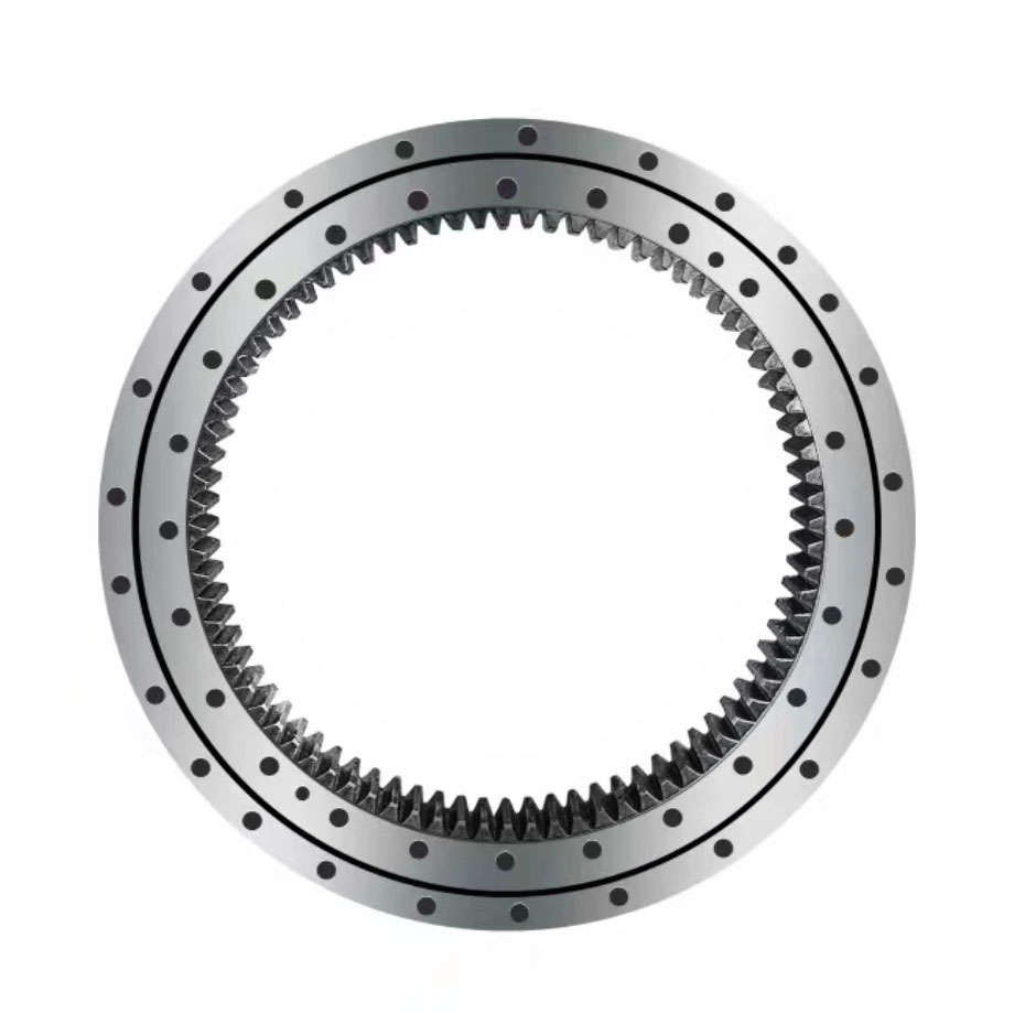
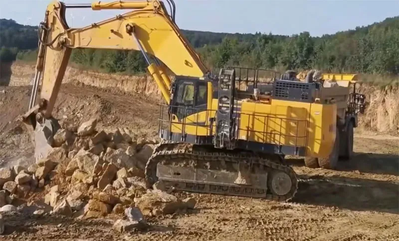
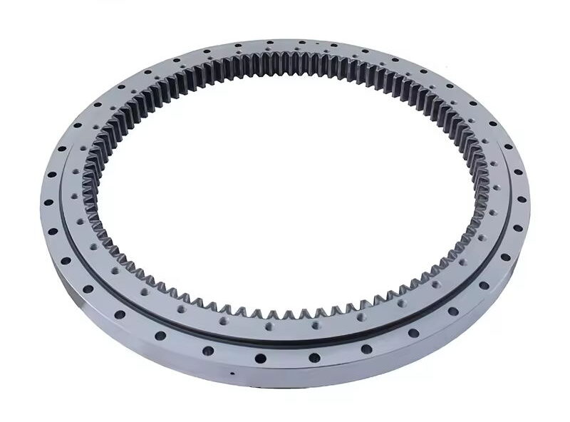
The slewing bearing is one of the essential components of an excavator, connecting the upper and lower frames and bearing the machine’s rotational movement. The part number for the slewing bearing of the PC600-7 excavator is 21M-25-11100. This slewing bearing has a high load capacity and long service life, maintaining stable performance in harsh working environments. The quality and performance of the slewing bearing directly affect the excavator’s efficiency and safety.

Ensuring the optimal performance and longevity of your Komatsu PC600-7 excavator requires a thorough and systematic inspection of its key components, including the slewing bearing. Here are the expanded and detailed steps for inspecting this critical part of your machinery:
By meticulously following the expanded inspection steps outlined above, you can gain a comprehensive understanding of the slewing bearing’s condition. This proactive approach allows you to identify and resolve potential issues before they escalate, ensuring the Komatsu PC600-7 excavator operates smoothly and efficiently. Regular inspections and maintenance of key components such as the main pump, actuators, directional control valve, and slewing bearing are essential for preventing hydraulic system failures and maintaining the excavator’s reliability and performance.
In summary, through detailed inspections and timely repairs, we successfully addressed the hydraulic system failures of the Komatsu PC600-7 excavator. This thorough approach restored the machine to its optimal operating condition, ensuring it can continue to perform its critical tasks effectively and reliably.