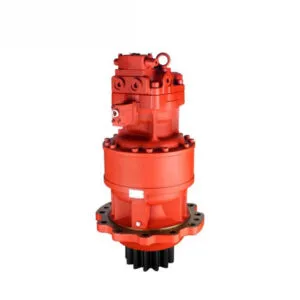
Quando la maniglia di comando viene messa in posizione di rotazione, l'olio di comando raggiunge la valvola di comando e spinge l'asta della valvola rotante per alimentare l'olio ad alta pressione fornito dalla pompa dell'olio di lavoro posteriore nel motore rotante; Allo stesso tempo, il circuito dell'olio che controlla il ritorno dell'olio al serbatoio viene interrotto, aumentando la pressione della valvola di rilascio del freno, spingendo il suo stelo per consentire a un altro olio ausiliario in pressione di entrare nel pistone del freno, aprendo il dispositivo del freno di rotazione e facendo agire il motore di rotazione.
Dal principio di funzionamento del meccanismo rotante, le cause del malfunzionamento sono tre: il circuito dell'olio di lavoro principale, la trasmissione meccanica e il circuito dell'olio di controllo.
Se la pressione del circuito dell'olio principale di oscillazione è bassa, non sarà possibile generare l'azione di oscillazione. Misurare la pressione del circuito principale dell'olio di lavoro. All'uscita di pressione della pompa dell'olio di lavoro posteriore è presente un tappo esagonale interno. Rimuoverlo e installare un manometro. Azionare la manopola per accelerare il motore diesel. La pressione misurata raggiunge i 23,5 MPa, che è la normale pressione di esercizio del sistema. Ciò indica che tutti i componenti idraulici del circuito principale dell'olio di lavoro sono normali.
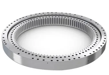
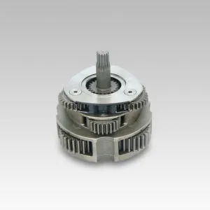
Il motore rotativo eroga la potenza attraverso il piccolo ingranaggio della trasmissione, che ruota intorno all'anello dell'ingranaggio rotante. Durante questo processo di erogazione della potenza, se gli ingranaggi che si ingranano tra loro sono inceppati, non ci sarà alcuna azione di rotazione.
In genere, un innesto anomalo della marcia può causare un rumore anomalo. Al momento, il conducente non ha sentito alcun rumore anomalo durante il funzionamento, quindi si possono temporaneamente escludere guasti meccanici alla trasmissione.
Poiché tutte le altre azioni dell'escavatore sono normali, ciò indica che la pompa dell'olio ausiliaria che fornisce la pressione dell'olio di controllo funziona normalmente. Esistono tre circuiti dell'olio di controllo per l'azione rotativa, ovvero il circuito dell'olio che controlla lo stelo della valvola rotativa, la valvola di rilascio del freno e il circuito dell'olio che entra nel pistone del freno di stazionamento. L'analisi specifica è la seguente.
Quando si aziona l'impugnatura rotante, toccando il tubo dell'olio di pressione del motore rotante si avverte un forte flusso d'olio, a indicare che l'olio della pressione di lavoro principale ha raggiunto il motore rotante, lo stelo della valvola rotante della valvola di controllo può essere aperto normalmente e il circuito dell'olio di controllo funziona normalmente. Misurare la pressione dell'olio al pistone del freno di stazionamento. Aprire il giunto del circuito dell'olio al motore rotativo, installare il giunto a tre vie e il manometro; la pressione misurata raggiunge i 4MPa, indicando che la pressione del circuito dell'olio è normale.
Misurare la pressione dell'olio alla valvola di rilascio del freno. Aprire il giunto del circuito dell'olio al motore rotativo, installare il giunto a tre vie e il manometro; la pressione misurata è di 0,4-0,6 MPa. Ovviamente, questa pressione è troppo bassa (la pressione di lavoro normale dovrebbe essere di 4MPa) per aprire la valvola di rilascio del freno, e l'olio di controllo dall'altro circuito non può fluire nel pistone del freno, per non parlare dell'apertura del dispositivo del freno rotante. Di conseguenza, non c'è azione nella rotazione. Le ragioni della bassa pressione in questo circuito dell'olio sono due. Una è che la valvola di controllo perde, causando la diminuzione della pressione dell'olio che entra nella valvola di rilascio del freno. (Collegando il manometro alla giunzione del tubo dell'olio di controllo dalla valvola di controllo alla valvola di rilascio del freno, la pressione dell'olio misurata è di soli 0,4-0,6 MPa, il che indica che il giudizio sulla perdita della valvola di controllo è corretto); la seconda ragione è che la valvola di rilascio del freno perde a causa dell'usura, il che aumenta il divario di accoppiamento (dopo lo smontaggio e l'ispezione, lo stelo e il foro della valvola si accoppiano bene e non si verificano fenomeni di inceppamento).
Excavators are complex pieces of machinery that rely heavily on their hydraulic systems to perform a variety of tasks, from digging and lifting to rotating and moving. One of the critical components in this hydraulic system is the control valve. The control valve regulates the flow and direction of hydraulic fluid, enabling precise control over the excavator’s movements. However, when a malfunction occurs, it can severely impact the performance and efficiency of the machine. This detailed guide delves into the process of troubleshooting a control valve malfunction, including the steps taken to diagnose the issue, the repair process, and the measures to prevent future problems.
Control valves are essential for directing hydraulic fluid to different parts of the excavator. They are responsible for controlling the flow rate and pressure of the hydraulic fluid, which in turn controls the speed and force of the machine’s movements. The primary functions of control valves in an excavator include:
Given their critical role, any malfunction in the control valve can lead to significant operational issues, such as erratic movements, reduced power, and complete failure of specific functions.
Before diving into the troubleshooting process, it’s essential to recognize the common symptoms of control valve malfunctions. These symptoms can help in early detection and prompt action to prevent further damage to the excavator. Common signs of control valve issues include:
The first step in troubleshooting a control valve malfunction is a thorough diagnosis. This involves a systematic approach to identify the root cause of the problem. Here’s a detailed breakdown of the diagnostic process:
Begin with a visual inspection of the control valve and the surrounding hydraulic components. Look for signs of wear, damage, or leaks. Pay close attention to the following:
The condition of the hydraulic fluid can provide valuable insights into the health of the control valve and the entire hydraulic system. Perform the following checks:
Pressure testing the hydraulic system can help identify issues related to fluid flow and pressure regulation. Use a hydraulic pressure gauge to perform the following tests:
Conduct functional tests to observe the performance of the control valve under different operating conditions. These tests can help pinpoint specific issues:
In this case study, the primary symptom observed was erratic rotational movements of the excavator. Upon conducting the above diagnostic steps, it was determined that the main cause of the malfunction was leakage in the control valve. Here’s a detailed analysis of the findings:
During the visual inspection, hydraulic fluid leaks were detected around the control valve area. The seals and gaskets appeared worn and deteriorated, indicating a potential source of the leakage.
The hydraulic fluid analysis revealed contamination with particles and moisture, which can accelerate wear and damage to the control valve components. The fluid’s color and viscosity suggested that it had not been changed according to the recommended maintenance schedule.
Pressure testing indicated significant pressure drops across the control valve, confirming internal leaks. The system pressure was also lower than the manufacturer’s specifications, further supporting the diagnosis of valve leakage.
Functional testing showed inconsistent and weak rotational movements, which aligned with the symptoms of control valve leakage. The directional control was also affected, with delays and difficulties in changing directions.
Given the complexity and critical role of the control valve, repairing it requires careful attention and expertise. Here’s a step-by-step guide to the repair process:
To access and repair the control valve, it is necessary to remove it from the excavator. This involves the following steps:
Once the control valve is removed, disassemble it to inspect and replace the damaged components. This involves:
After replacing the damaged components, reassemble the control valve with careful attention to detail:
With the control valve repaired and reassembled, reinstall it into the excavator:
After reinstalling the control valve, perform comprehensive tests to ensure that the repair was successful:
To prevent future control valve malfunctions and ensure the longevity of the excavator’s hydraulic system, implement the following maintenance practices:
Regularly check the hydraulic fluid level and quality, and change it according to the manufacturer’s recommendations. Using clean, high-quality hydraulic fluid helps prevent contamination and reduces wear on the control valve components.
Inspect seals and gaskets regularly for signs of wear and deterioration. Replace them as needed to prevent leaks and maintain optimal pressure within the hydraulic system.
Implement a regular maintenance schedule that includes checking the condition of the control valve, hydraulic lines, and other components. Timely maintenance helps identify and address potential issues before they lead to significant malfunctions.
Ensure that operators are trained in the correct use and maintenance of the excavator’s hydraulic system. Proper operation and handling can reduce the risk of damage and prolong the lifespan of the control valve and other components.
Always use genuine parts and components that meet the manufacturer’s specifications when repairing or replacing parts of the hydraulic system. This ensures compatibility and reliability, reducing the risk of future malfunctions.