Amikor a működtető fogantyú forgatási helyzetbe kerül, a vezérlőolaj eléri a vezérlőszelepet, és megnyomja a forgószelep rúdját, hogy a hátsó munkaolajszivattyú által biztosított nagynyomású olajat a forgómotorba juttassa; Ezzel egyidejűleg a tartályba történő olajvisszavezetést vezérlő olajkör megszakad, megnövelve a fékkioldó szelep nyomását, annak szelepszárát lenyomva, hogy egy másik segédnyomású olaj juthasson a fékdugattyúba, kinyitva a lengőfék-berendezést, és működésbe hozva a lengőmotort; A forgó motor a sebességváltó kis fogaskerekén keresztül adja le a teljesítményt, amely a forgó fogaskerék gyűrűjével összefogva forgó mozgást hoz létre.
A forgó mechanizmus működési elve alapján a meghibásodásnak három oka van, nevezetesen a fő munkaolajkör, a mechanikus átvitel és a vezérlőolajkör.
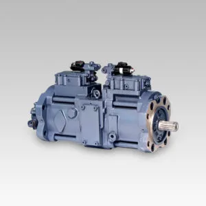
Ha a lengő főolajkör nyomása alacsony, nem lehet lengőhatást létrehozni. Mérje meg a fő üzemi olajkör rendszerének nyomását. A hátsó munkaolajszivattyú nyomáskimeneténél van egy belső hatszögletű olajdugó. Távolítsa el, és szereljen be egy nyomásmérőt. A dízelmotor gyorsításához működtesse a forgókart. A mért nyomás eléri a 23,5MPa-t, ami a rendszer normál üzemi nyomása. Ez azt jelzi, hogy a fő munkaolajkörben lévő összes hidraulikus alkatrész rendben van.
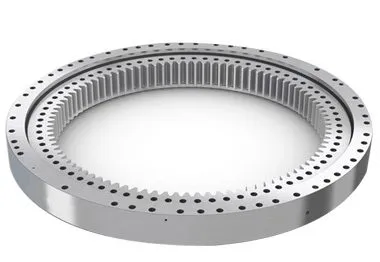
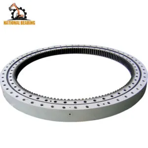
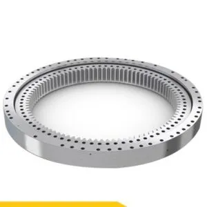
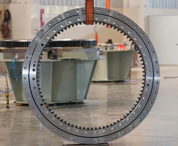
A forgómotor az erőátvitel kis fogaskerekén keresztül adja le a teljesítményt, amely a forgó fogaskerék körül forog. E teljesítményleadási folyamat során, ha az egymásba fogó fogaskerekek elakadnak, akkor nem lesz forgási művelet sem.
Általában a rendellenes sebességváltó-beállás okozhat rendellenes zajt. Jelenleg a járművezető nem hallott rendellenes hangot működés közben, így a mechanikus váltóhiba ideiglenesen kizárható.
Mivel a kotrógép minden más művelete normális, ez azt jelzi, hogy a vezérlőolajnyomást biztosító segédolajszivattyú normálisan működik. Három vezérlőolaj-kör van a forgási művelethez, nevezetesen a forgókarszelepet vezérlő olajkör, a fékkioldó szelep és a rögzítőfék dugattyújába kerülő olajkör. A konkrét elemzés a következő.
A forgókar működtetésekor a forgómotor nyomóolajcsövének érintésekor erős olajfolyás jelentkezik, ami azt jelzi, hogy a fő üzemi nyomású olaj elérte a forgómotort, a vezérlőszelep forgókarszárát normálisan ki lehet nyitni, és a vezérlőolaj-kör normálisan működik. Mérje meg az olajnyomást a rögzítőfék dugattyújához. Nyissa ki az olajkör csőcsatlakozását a forgómotorhoz, szerelje fel a háromutas csatlakozót és a nyomásmérőt, és a mért nyomás eléri a 4MPa-t, ami azt jelzi, hogy az olajkör nyomása normális.
Mérje meg az olajnyomást a fékkioldó szelephez. Nyissa ki az olajkör csőcsatlakozását a forgódugattyús motorhoz, szerelje fel a háromutas csatlakozót és a nyomásmérőt, és a mért nyomás 0,4-0,6MPa. Nyilvánvaló, hogy ez a nyomás túl alacsony (a normál üzemi nyomásnak 4MPa-nak kell lennie) a fékkioldó szelep kinyitásához, és a másik körből származó vezérlőolaj nem tud a fékdugattyúba áramlani, nemhogy kinyitni a forgó fékberendezést. Ezért a forgatásban nincs hatás. Két oka van az alacsony nyomásnak ebben az olajkörben. Az egyik az, hogy a vezérlőszelep szivárog, ami miatt a fékkioldószelepbe belépő olajnyomás csökken. (Csatlakoztassa a nyomásmérőt a vezérlőolajcső csőcsatlakozásához a vezérlőszeleptől a fékkioldószelephez, és a mért olajnyomás csak 0,4-0,6MPa, ami azt jelzi, hogy a vezérlőszelep szivárgásának megítélése helyes); A második ok az, hogy a fékkioldószelep az elhasználódás miatt szivárog, ami növeli az illesztési hézagot (szétszerelés és ellenőrzés után a szelepszár és a szelepfurat jól illeszkedik, és nincs elakadási jelenség).
Excavators are complex pieces of machinery that rely heavily on their hydraulic systems to perform a variety of tasks, from digging and lifting to rotating and moving. One of the critical components in this hydraulic system is the control valve. The control valve regulates the flow and direction of hydraulic fluid, enabling precise control over the excavator’s movements. However, when a malfunction occurs, it can severely impact the performance and efficiency of the machine. This detailed guide delves into the process of troubleshooting a control valve malfunction, including the steps taken to diagnose the issue, the repair process, and the measures to prevent future problems.
Control valves are essential for directing hydraulic fluid to different parts of the excavator. They are responsible for controlling the flow rate and pressure of the hydraulic fluid, which in turn controls the speed and force of the machine’s movements. The primary functions of control valves in an excavator include:
Given their critical role, any malfunction in the control valve can lead to significant operational issues, such as erratic movements, reduced power, and complete failure of specific functions.
Before diving into the troubleshooting process, it’s essential to recognize the common symptoms of control valve malfunctions. These symptoms can help in early detection and prompt action to prevent further damage to the excavator. Common signs of control valve issues include:
The first step in troubleshooting a control valve malfunction is a thorough diagnosis. This involves a systematic approach to identify the root cause of the problem. Here’s a detailed breakdown of the diagnostic process:
Begin with a visual inspection of the control valve and the surrounding hydraulic components. Look for signs of wear, damage, or leaks. Pay close attention to the following:
The condition of the hydraulic fluid can provide valuable insights into the health of the control valve and the entire hydraulic system. Perform the following checks:
Pressure testing the hydraulic system can help identify issues related to fluid flow and pressure regulation. Use a hydraulic pressure gauge to perform the following tests:
Conduct functional tests to observe the performance of the control valve under different operating conditions. These tests can help pinpoint specific issues:
In this case study, the primary symptom observed was erratic rotational movements of the excavator. Upon conducting the above diagnostic steps, it was determined that the main cause of the malfunction was leakage in the control valve. Here’s a detailed analysis of the findings:
During the visual inspection, hydraulic fluid leaks were detected around the control valve area. The seals and gaskets appeared worn and deteriorated, indicating a potential source of the leakage.
The hydraulic fluid analysis revealed contamination with particles and moisture, which can accelerate wear and damage to the control valve components. The fluid’s color and viscosity suggested that it had not been changed according to the recommended maintenance schedule.
Pressure testing indicated significant pressure drops across the control valve, confirming internal leaks. The system pressure was also lower than the manufacturer’s specifications, further supporting the diagnosis of valve leakage.
Functional testing showed inconsistent and weak rotational movements, which aligned with the symptoms of control valve leakage. The directional control was also affected, with delays and difficulties in changing directions.
Given the complexity and critical role of the control valve, repairing it requires careful attention and expertise. Here’s a step-by-step guide to the repair process:
To access and repair the control valve, it is necessary to remove it from the excavator. This involves the following steps:
Once the control valve is removed, disassemble it to inspect and replace the damaged components. This involves:
After replacing the damaged components, reassemble the control valve with careful attention to detail:
With the control valve repaired and reassembled, reinstall it into the excavator:
After reinstalling the control valve, perform comprehensive tests to ensure that the repair was successful:
To prevent future control valve malfunctions and ensure the longevity of the excavator’s hydraulic system, implement the following maintenance practices:
Regularly check the hydraulic fluid level and quality, and change it according to the manufacturer’s recommendations. Using clean, high-quality hydraulic fluid helps prevent contamination and reduces wear on the control valve components.
Inspect seals and gaskets regularly for signs of wear and deterioration. Replace them as needed to prevent leaks and maintain optimal pressure within the hydraulic system.
Implement a regular maintenance schedule that includes checking the condition of the control valve, hydraulic lines, and other components. Timely maintenance helps identify and address potential issues before they lead to significant malfunctions.
Ensure that operators are trained in the correct use and maintenance of the excavator’s hydraulic system. Proper operation and handling can reduce the risk of damage and prolong the lifespan of the control valve and other components.
Always use genuine parts and components that meet the manufacturer’s specifications when repairing or replacing parts of the hydraulic system. This ensures compatibility and reliability, reducing the risk of future malfunctions.