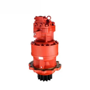
Når betjeningshåndtaget placeres i rotationspositionen, når kontrololien kontrolventilen og skubber den roterende ventilstang for at føre højtryksolien fra den bageste arbejdsoliepumpe ind i den roterende motor; Samtidig afbrydes oliekredsløbet, der styrer oliereturneringen til tanken, hvilket øger trykket i bremseudløsningsventilen, skubber ventilspindlen for at lade en anden hjælpetryksolie komme ind i bremsestemplet, åbner svingbremseanordningen og får svingmotoren til at virke; Den roterende motor afgiver kraft gennem gearkassens lille gear, som griber ind i den roterende gearring for at generere en roterende bevægelse.
Ud fra arbejdsprincippet for den roterende mekanisme er der tre grunde til fejlfunktionen, nemlig det vigtigste arbejdsoliekredsløb, den mekaniske transmission og kontrololiekredsløbet.
Hvis trykket i det svingende hovedoliekredsløb er lavt, vil det ikke være muligt at generere svingning. Mål trykket i det primære arbejdsoliekredsløbssystem. Der er en indvendig sekskantet olieprop ved trykudtaget på den bageste arbejdsoliepumpe. Fjern den, og monter en trykmåler. Betjen drejehåndtaget for at accelerere dieselmotoren. Det målte tryk når 23,5 MPa, hvilket er systemets normale arbejdstryk. Dette indikerer, at alle hydrauliske komponenter i hovedarbejdsoliekredsløbet er normale.
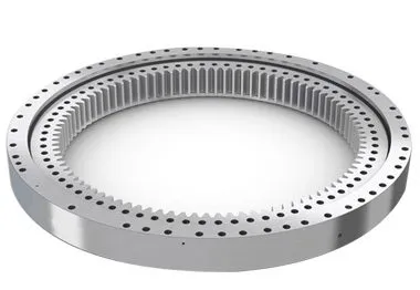
Den roterende motor afgiver kraft gennem det lille gear i transmissionen, som roterer rundt om den roterende gearring. Hvis de tandhjul, der griber ind i hinanden, sidder fast under denne kraftudvekslingsproces, vil der heller ikke være nogen rotation.
Generelt kan unormalt gearindgreb forårsage unormal støj. I øjeblikket har føreren ikke hørt nogen unormal lyd under drift, så mekaniske transmissionsfejl kan midlertidigt udelukkes.
Da alle gravemaskinens andre funktioner er normale, tyder det på, at den ekstra oliepumpe, der leverer kontrololietryk, fungerer normalt. Der er tre kontrololiekredsløb til den roterende handling, nemlig det oliekredsløb, der styrer den roterende ventilspindel, bremseudløsningsventilen og det oliekredsløb, der kommer ind i parkeringsbremsestemplet. Den specifikke analyse er som følger.
Når du betjener drejehåndtaget, er der en stærk olieinfluenza, når du rører ved drejemotorens trykolierør, hvilket indikerer, at den vigtigste arbejdstrykolie har nået drejemotoren, at reguleringsventilens drejeventilspindel kan åbnes normalt, og at reguleringsoliekredsløbet fungerer normalt. Mål olietrykket til parkeringsbremsestemplet. Åbn rørforbindelsen i oliekredsløbet til den roterende motor, installer trevejsforbindelsen og trykmåleren, og det målte tryk når 4MPa, hvilket indikerer, at trykket i oliekredsløbet er normalt.
Mål olietrykket til bremseudløsningsventilen. Åbn rørleddet i oliekredsløbet til den roterende motor, installer trevejsleddet og trykmåleren, og det målte tryk er 0,4-0,6MPa. Det er klart, at dette tryk er for lavt (normalt arbejdstryk skal være 4MPa) til at åbne bremseudløsningsventilen, og kontrololien fra det andet kredsløb kan ikke strømme ind i bremsestemplet, endsige åbne den roterende bremseanordning. Derfor er der ingen handling i rotationen. Der er to grunde til det lave tryk i dette oliekredsløb. Den ene er, at kontrolventilen lækker, hvilket får olietrykket, der kommer ind i bremseløsningsventilen, til at falde. (Tilslut trykmåleren til rørforbindelsen på kontrololierøret fra kontrolventilen til bremseudløserventilen, og det målte olietryk er kun 0,4-0,6 MPa, hvilket indikerer, at vurderingen af kontrolventilens lækage er korrekt.); Den anden grund er, at bremseudløserventilen lækker på grund af slitage, hvilket øger pasningsgabet (efter demontering og inspektion passer ventilspindlen og ventilhullet godt, og der er ikke noget fastklemningsfænomen).
Excavators are complex pieces of machinery that rely heavily on their hydraulic systems to perform a variety of tasks, from digging and lifting to rotating and moving. One of the critical components in this hydraulic system is the control valve. The control valve regulates the flow and direction of hydraulic fluid, enabling precise control over the excavator’s movements. However, when a malfunction occurs, it can severely impact the performance and efficiency of the machine. This detailed guide delves into the process of troubleshooting a control valve malfunction, including the steps taken to diagnose the issue, the repair process, and the measures to prevent future problems.
Control valves are essential for directing hydraulic fluid to different parts of the excavator. They are responsible for controlling the flow rate and pressure of the hydraulic fluid, which in turn controls the speed and force of the machine’s movements. The primary functions of control valves in an excavator include:
Given their critical role, any malfunction in the control valve can lead to significant operational issues, such as erratic movements, reduced power, and complete failure of specific functions.
Before diving into the troubleshooting process, it’s essential to recognize the common symptoms of control valve malfunctions. These symptoms can help in early detection and prompt action to prevent further damage to the excavator. Common signs of control valve issues include:
The first step in troubleshooting a control valve malfunction is a thorough diagnosis. This involves a systematic approach to identify the root cause of the problem. Here’s a detailed breakdown of the diagnostic process:
Begin with a visual inspection of the control valve and the surrounding hydraulic components. Look for signs of wear, damage, or leaks. Pay close attention to the following:
The condition of the hydraulic fluid can provide valuable insights into the health of the control valve and the entire hydraulic system. Perform the following checks:
Pressure testing the hydraulic system can help identify issues related to fluid flow and pressure regulation. Use a hydraulic pressure gauge to perform the following tests:
Conduct functional tests to observe the performance of the control valve under different operating conditions. These tests can help pinpoint specific issues:
In this case study, the primary symptom observed was erratic rotational movements of the excavator. Upon conducting the above diagnostic steps, it was determined that the main cause of the malfunction was leakage in the control valve. Here’s a detailed analysis of the findings:
During the visual inspection, hydraulic fluid leaks were detected around the control valve area. The seals and gaskets appeared worn and deteriorated, indicating a potential source of the leakage.
The hydraulic fluid analysis revealed contamination with particles and moisture, which can accelerate wear and damage to the control valve components. The fluid’s color and viscosity suggested that it had not been changed according to the recommended maintenance schedule.
Pressure testing indicated significant pressure drops across the control valve, confirming internal leaks. The system pressure was also lower than the manufacturer’s specifications, further supporting the diagnosis of valve leakage.
Functional testing showed inconsistent and weak rotational movements, which aligned with the symptoms of control valve leakage. The directional control was also affected, with delays and difficulties in changing directions.
Given the complexity and critical role of the control valve, repairing it requires careful attention and expertise. Here’s a step-by-step guide to the repair process:
To access and repair the control valve, it is necessary to remove it from the excavator. This involves the following steps:
Once the control valve is removed, disassemble it to inspect and replace the damaged components. This involves:
After replacing the damaged components, reassemble the control valve with careful attention to detail:
With the control valve repaired and reassembled, reinstall it into the excavator:
After reinstalling the control valve, perform comprehensive tests to ensure that the repair was successful:
To prevent future control valve malfunctions and ensure the longevity of the excavator’s hydraulic system, implement the following maintenance practices:
Regularly check the hydraulic fluid level and quality, and change it according to the manufacturer’s recommendations. Using clean, high-quality hydraulic fluid helps prevent contamination and reduces wear on the control valve components.
Inspect seals and gaskets regularly for signs of wear and deterioration. Replace them as needed to prevent leaks and maintain optimal pressure within the hydraulic system.
Implement a regular maintenance schedule that includes checking the condition of the control valve, hydraulic lines, and other components. Timely maintenance helps identify and address potential issues before they lead to significant malfunctions.
Ensure that operators are trained in the correct use and maintenance of the excavator’s hydraulic system. Proper operation and handling can reduce the risk of damage and prolong the lifespan of the control valve and other components.
Always use genuine parts and components that meet the manufacturer’s specifications when repairing or replacing parts of the hydraulic system. This ensures compatibility and reliability, reducing the risk of future malfunctions.