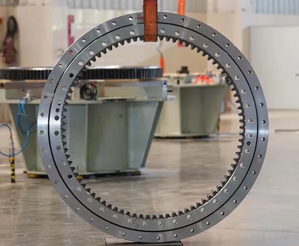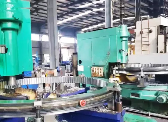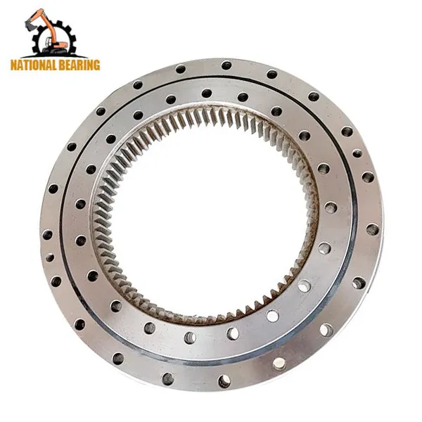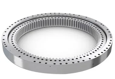
Když je ovládací rukojeť v poloze pro otáčení, řídicí olej se dostane k řídicímu ventilu a tlačí na táhlo otočného ventilu, aby se do otočného motoru dostal vysokotlaký olej dodávaný zadním pracovním olejovým čerpadlem; Současně se přeruší olejový okruh, který řídí návrat oleje do nádrže, čímž se zvýší tlak v uvolňovacím ventilu brzdy, zatlačí se na jeho ventilovou tyč, aby se do brzdového pístu dostal další pomocný tlakový olej, otevře se zařízení kyvné brzdy a začne působit kyvný motor; rotační motor vyvozuje výkon přes malý převod převodovky, který se spojí s otočným ozubeným kroužkem a vytvoří rotační pohyb.

Z principu fungování rotačního mechanismu vyplývají tři příčiny poruchy, a to hlavní pracovní olejový okruh, mechanický převod a kontrolní olejový okruh.
Pokud je tlak v hlavním olejovém okruhu kyvného motoru nízký, není možné vytvořit kyvnou akci. Změřte tlak v systému hlavního pracovního olejového okruhu. Na výstupu tlaku zadního pracovního olejového čerpadla je vnitřní šestihranná olejová zátka. Vyjměte ji a nainstalujte tlakoměr. Ovládejte otočnou rukojeť pro zrychlení vznětového motoru. Naměřený tlak dosáhne 23,5 MPa, což je normální pracovní tlak systému. To znamená, že všechny hydraulické součásti hlavního okruhu pracovního oleje jsou v normálu.

Rotační motor přenáší výkon přes malé ozubené kolo převodovky, které se otáčí kolem rotačního ozubeného kroužku. Pokud se během tohoto procesu výstupu výkonu zaseknou ozubená kola, která se vzájemně propojují, nedojde ani k otáčení.
Obecně může abnormální záběr převodovky způsobovat abnormální hluk. V současné době řidič během provozu neslyšel žádný abnormální zvuk, takže mechanické závady převodovky lze dočasně vyloučit.
Protože všechny ostatní činnosti rýpadla jsou normální, znamená to, že pomocné olejové čerpadlo, které zajišťuje kontrolní tlak oleje, pracuje normálně. Existují tři okruhy řídicího oleje pro rotační činnost, a to olejový okruh, který ovládá dřík rotačního ventilu, uvolňovací ventil brzdy a olejový okruh, který vstupuje do pístu parkovací brzdy. Konkrétní analýza je následující.
Při ovládání otočné rukojeti se při dotyku tlakové olejové trubky otočného motoru objeví silný olejový proud, což znamená, že hlavní pracovní tlakový olej dosáhl otočného motoru, dřík otočného ventilu ovládacího ventilu lze normálně otevřít a okruh ovládacího oleje funguje normálně. Změřte tlak oleje na píst parkovací brzdy. Otevřete trubkový spoj olejového okruhu k rotačnímu motoru, nainstalujte trojcestný spoj a tlakoměr a naměřený tlak dosáhne 4 MPa, což znamená, že tlak olejového okruhu je normální.
Změřte tlak oleje na uvolňovací ventil brzd. Otevřete trubkový spoj olejového okruhu k rotačnímu motoru, nainstalujte trojcestný spoj a manometr a naměřený tlak je 0,4-0,6 MPa. Je zřejmé, že tento tlak je příliš nízký (normální pracovní tlak by měl být 4 MPa) na otevření uvolňovacího ventilu brzdy a řídicí olej z druhého okruhu nemůže proudit do brzdového pístu, natož aby otevřel zařízení rotační brzdy. Proto nedochází k žádnému působení při otáčení. Nízký tlak v tomto olejovém okruhu má dvě příčiny. Jedním z nich je, že řídicí ventil netěsní, což způsobuje pokles tlaku oleje vstupujícího do uvolňovacího ventilu brzd. (Připojte tlakoměr ke spoji potrubí ovládacího olejového potrubí od ovládacího ventilu k uvolňovacímu ventilu brzd a naměřený tlak oleje je pouze 0,4-0,6 MPa, což znamená, že úsudek o netěsnosti ovládacího ventilu je správný); Druhým důvodem je, že uvolňovací ventil brzd netěsní v důsledku opotřebení, což zvyšuje mezeru uložení (po demontáži a kontrole dřík ventilu a otvor ventilu dobře sedí a nedochází k žádnému jevu zasekávání).
Excavators are complex pieces of machinery that rely heavily on their hydraulic systems to perform a variety of tasks, from digging and lifting to rotating and moving. One of the critical components in this hydraulic system is the control valve. The control valve regulates the flow and direction of hydraulic fluid, enabling precise control over the excavator’s movements. However, when a malfunction occurs, it can severely impact the performance and efficiency of the machine. This detailed guide delves into the process of troubleshooting a control valve malfunction, including the steps taken to diagnose the issue, the repair process, and the measures to prevent future problems.
Control valves are essential for directing hydraulic fluid to different parts of the excavator. They are responsible for controlling the flow rate and pressure of the hydraulic fluid, which in turn controls the speed and force of the machine’s movements. The primary functions of control valves in an excavator include:
Given their critical role, any malfunction in the control valve can lead to significant operational issues, such as erratic movements, reduced power, and complete failure of specific functions.
Before diving into the troubleshooting process, it’s essential to recognize the common symptoms of control valve malfunctions. These symptoms can help in early detection and prompt action to prevent further damage to the excavator. Common signs of control valve issues include:
The first step in troubleshooting a control valve malfunction is a thorough diagnosis. This involves a systematic approach to identify the root cause of the problem. Here’s a detailed breakdown of the diagnostic process:
Begin with a visual inspection of the control valve and the surrounding hydraulic components. Look for signs of wear, damage, or leaks. Pay close attention to the following:
The condition of the hydraulic fluid can provide valuable insights into the health of the control valve and the entire hydraulic system. Perform the following checks:
Pressure testing the hydraulic system can help identify issues related to fluid flow and pressure regulation. Use a hydraulic pressure gauge to perform the following tests:
Conduct functional tests to observe the performance of the control valve under different operating conditions. These tests can help pinpoint specific issues:
In this case study, the primary symptom observed was erratic rotational movements of the excavator. Upon conducting the above diagnostic steps, it was determined that the main cause of the malfunction was leakage in the control valve. Here’s a detailed analysis of the findings:
During the visual inspection, hydraulic fluid leaks were detected around the control valve area. The seals and gaskets appeared worn and deteriorated, indicating a potential source of the leakage.
The hydraulic fluid analysis revealed contamination with particles and moisture, which can accelerate wear and damage to the control valve components. The fluid’s color and viscosity suggested that it had not been changed according to the recommended maintenance schedule.
Pressure testing indicated significant pressure drops across the control valve, confirming internal leaks. The system pressure was also lower than the manufacturer’s specifications, further supporting the diagnosis of valve leakage.
Functional testing showed inconsistent and weak rotational movements, which aligned with the symptoms of control valve leakage. The directional control was also affected, with delays and difficulties in changing directions.
Given the complexity and critical role of the control valve, repairing it requires careful attention and expertise. Here’s a step-by-step guide to the repair process:
To access and repair the control valve, it is necessary to remove it from the excavator. This involves the following steps:
Once the control valve is removed, disassemble it to inspect and replace the damaged components. This involves:
After replacing the damaged components, reassemble the control valve with careful attention to detail:
With the control valve repaired and reassembled, reinstall it into the excavator:
After reinstalling the control valve, perform comprehensive tests to ensure that the repair was successful:
To prevent future control valve malfunctions and ensure the longevity of the excavator’s hydraulic system, implement the following maintenance practices:
Regularly check the hydraulic fluid level and quality, and change it according to the manufacturer’s recommendations. Using clean, high-quality hydraulic fluid helps prevent contamination and reduces wear on the control valve components.
Inspect seals and gaskets regularly for signs of wear and deterioration. Replace them as needed to prevent leaks and maintain optimal pressure within the hydraulic system.
Implement a regular maintenance schedule that includes checking the condition of the control valve, hydraulic lines, and other components. Timely maintenance helps identify and address potential issues before they lead to significant malfunctions.
Ensure that operators are trained in the correct use and maintenance of the excavator’s hydraulic system. Proper operation and handling can reduce the risk of damage and prolong the lifespan of the control valve and other components.
Always use genuine parts and components that meet the manufacturer’s specifications when repairing or replacing parts of the hydraulic system. This ensures compatibility and reliability, reducing the risk of future malfunctions.
